03 — Photos & Media
See the work
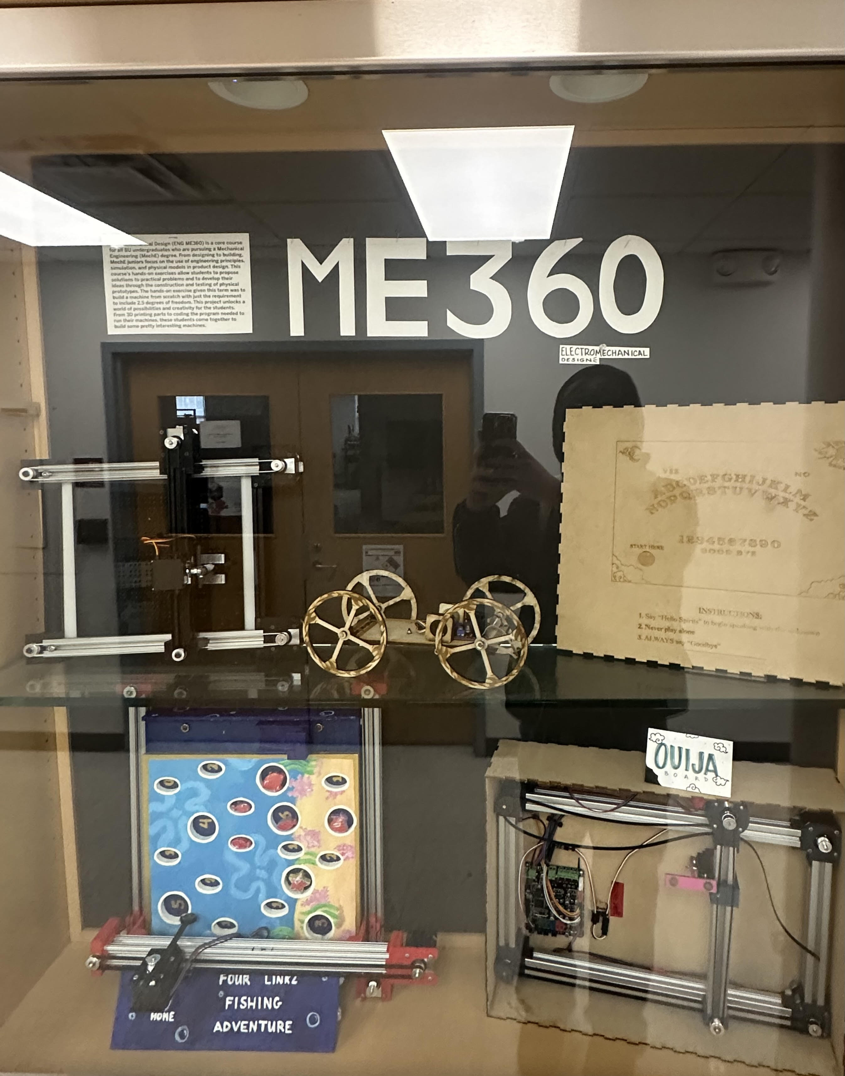
Cart assembled on track
Replace with <img> or <video>
Replace with <img> or <video>
Replace placeholders with your project photos
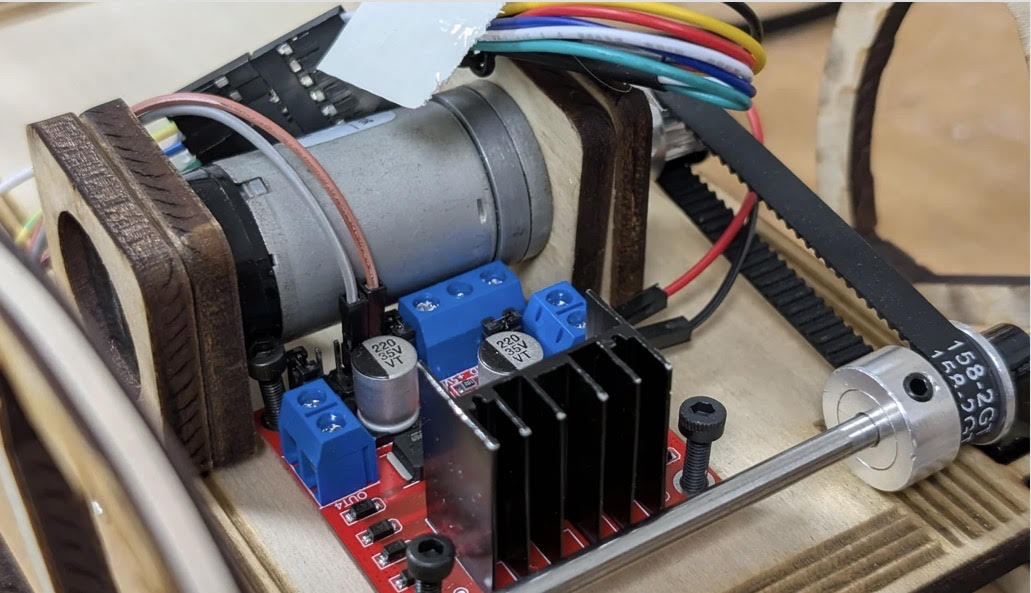
Electronics & encoder wiring
 -->
-->
CAD chassis model
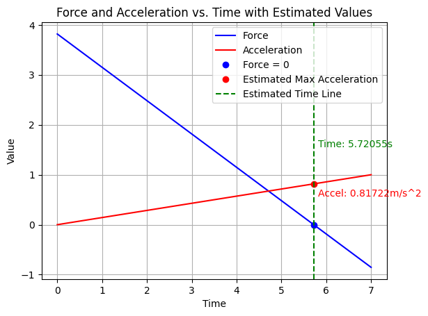
Speed data plot
A motorized cart with closed-loop speed control using encoder feedback and an Arduino controller.
Design a motorized cart capable of maintaining a target speed under a set load condition using closed-loop control.
Implement sensor-based feedback using encoders and a proportional control algorithm on an Arduino microcontroller.
Build a fast, stable cart that completes a 10‑foot out‑and‑back run without tipping a balance bar, guided by simulation and validated through testing.
Replace placeholders with your project photos
-->
Built a simulation workflow using SolidWorks motion data and custom Python/Arduino scripts. Extracted maximum non‑tipping acceleration from SolidWorks, then used that acceleration and the motor’s max angular velocity to determine the required wheel radius for matching the ideal velocity profile.
Modeled the full cart assembly in SolidWorks, including wheel geometry, motor placement, and bar‑support structure. Verified center‑of‑gravity location and ensured the chassis could withstand the acceleration profile without risking bar tip‑over.
Laser‑cut all structural components due to 3D‑printer backlog. This reduced turnaround time and produced dimensionally consistent parts. Wheel radius was finalized at 2.3155", then reduced to 2.3055" to compensate for added rubber‑band traction increasing effective diameter.
Developed two core scripts: Analysis code to compute max acceleration, velocity, and wheel radius using SolidWorks‑exported data. Motor characterization code to determine the motor’s maximum angular velocity. The Arduino Uno processed digital encoder inputs and generated PWM outputs on pins 5 and 6, routed through an H‑Bridge to deliver 12 V and directional control to the motor.
Ran repeated forward‑and‑return trials to validate the simulated velocity profile. Identified the need for a distance multiplier due to the motor’s slow ramp‑up from PWM_MIN = 25 RPM, which delayed actual motion. Attempts to increase PWM_MIN caused immediate ±55 RPM reversals, introducing a jerk that tipped the bar and prevented encoder‑based distance control.
The cart successfully supported the 12×1×1‑inch bar throughout motion and achieved a fast, stable run under the non‑tipping acceleration limit.
The final wheel radius closely matched the simulation derived requirement, and the laser‑cut chassis aligned with the SolidWorks model within practical tolerance.
Simulation‑based acceleration and wheel‑radius predictions translated well to real‑world performance, validating the analytical workflow.
Primary performance limitation was distance accuracy: the time‑based motion profile assumed instantaneous motor response, but the motor’s low‑speed ramp‑up reduced effective travel distance. Increasing minimum PWM resolved the lag but introduced instability and bar‑tipping due to abrupt direction changes.