ME360 Cart Project
PROJECT OVERVIEW: The goal of this project was to create a cart that could go forward a set distance (10 feet in simulation) and back to the starting position without tipping a 12 x 1 x 1 inch bar as fast as possible. Tasked with using simulation and math to calculate the hypothetical max acceleration, velocity, and wheel radius in order to get our cart to move as fast as possible, then test hypothical results in real world scenario and find actual values.
Cart Simulation Videos
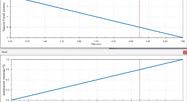
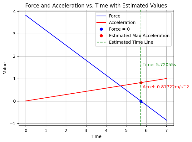
Simulation used to find max acceleration of the cart. Used acceleration vs. time graph with reaction force vs time graph to find when the front of the bar had a reaction force of 0 meaning it was almost about to tip.
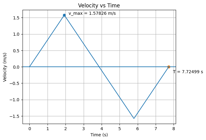
Shows simulation of how the cart is going to accelerate and decelerate going from 10 feet and then back to starting position with the proper wheel radius and angular acceleration/velocity.
Fully Assembled Cart Videos
Video of Test run of Cart once fully assemblied and code uploaded.
Design Process
Used SolidWorks and Coding to figure out max acceleration the cart could travel at without tipping the bar. After we used the max acceleration along with the max angular velocity of the motor to calculate the radius of the wheels that would be needed to match the linear velocity profile of the cart simulation without wheels.
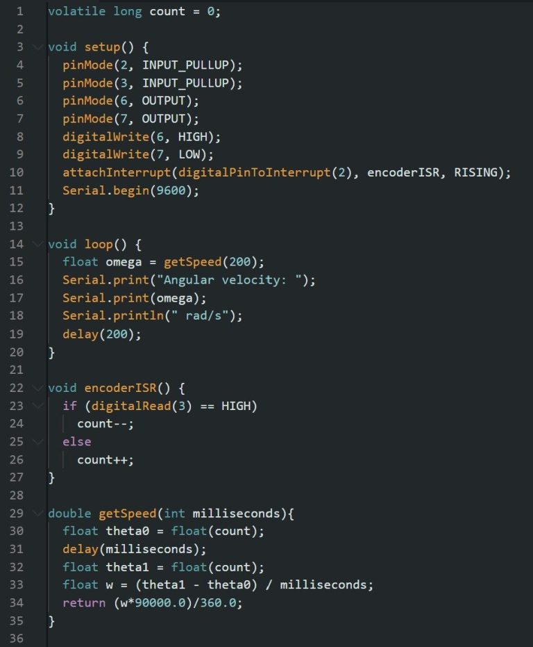
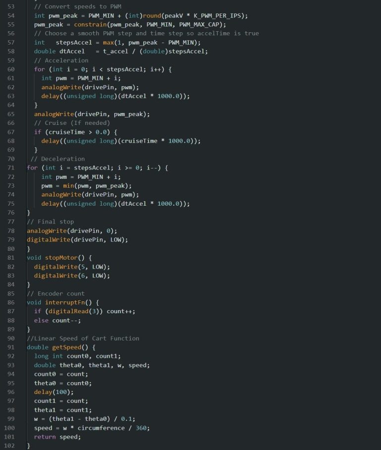
Design Process Code
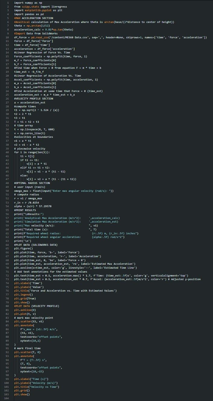
Two codes used in the design process. The first one was to find all of our values such as max acceleration (from SolidWorks exported data). The second code was used to find the max angular velocity.
Final Design and Code
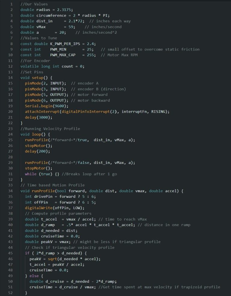
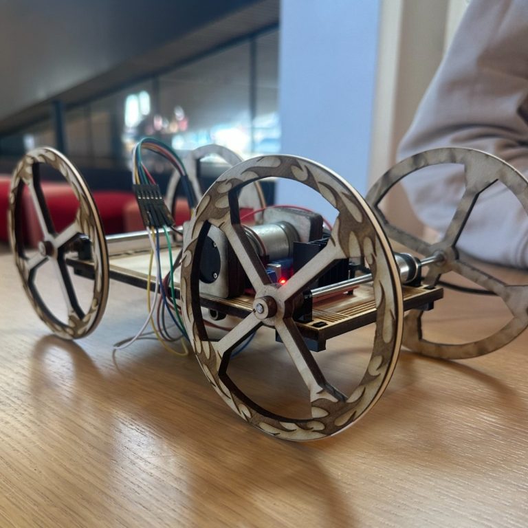
For our final design we laser cut all of our parts, because of the 3D printers being backed up, which worked very well and was very quick. Our final wheel radius was 2.3155'' which we reduced to 2.3055'' because we decided to add rubberbands around our wooden laser cut wheels to add traction which increased the diameter of our wheels.
For the wiring, the Arduino Uno processed digital inputs and produced analog output signals. In this setup, the motor receives analog signals from pins 5 and 6 of the Arduino, which are routed through the H-Bridge to boost the voltage to 12 V and decide which direction to drive before powering the motor.
Final Design Videos
Final Design Results
Our cart was great at holding up the bar and going at a relatively fast pace, the problem we ran into was our distance the cart traveled. The reason this was a problem was because a distance multiplier was needed because the motion code was time-based, but the motor required time to ramp from a very low starting speed (PMW_MIN = 25 RPM) before the cart actually began moving, shortening the effective velocity profile. Increasing PMW_MIN to fix this caused instability because the motor would instantly switch from +55 RPM to −55 RPM when reversing, creating a jerk that tipped the bar and also prevented a distance-based profile from working since the encoder could not register motion at lower speeds.
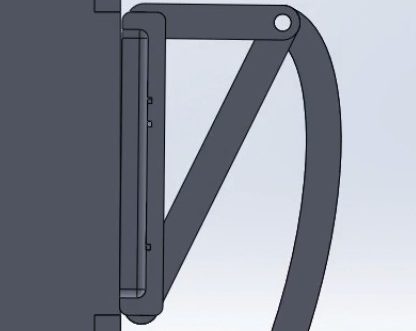
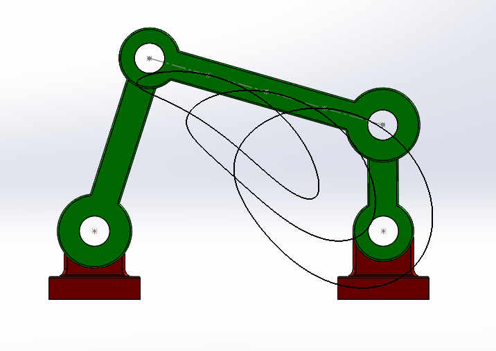
4 Bar Mechanism
PROJECT OVERVIEW: Created a 4 bar mechanism with two stationary bearings, crank rocker, and extension links to study the motion of 4 bar systems for upcoming project (Trashcan Project).
Graphs and Results
The maximum value of the motor torque with a 20 RPM motor I found to be 678.0123 Nmm which occurred when the crank was an angle of -66.879 degrees off of the vertical.
Each Bearing experienced a reaction force with the right bearing having a max reaction force of 16.80993 Newtons and the left bearing having a max reaction force of 14.22265 Newtons.
Later the Mechanism was tested at 600 RPMs and the value of 10,568.38 Nmm was found to be the maximum motor torque which means you would need a motor that could produce at least 10,568.38 Nmm to drive the crank at 600 RPMs.
Negative motor torque occurs when the motion of the links assist the cranks rotation instead of opposing it. For example when gravity or inertia of the extension or rocker link pull the crank in the correct direction you would experience negative torque.
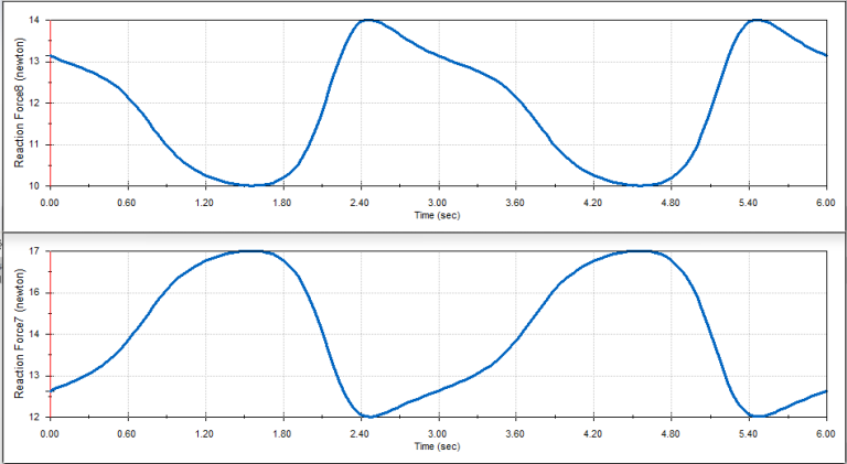
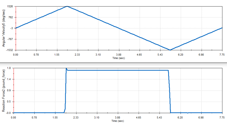
Reaction force on Left (top) and Right (bottom) bearings
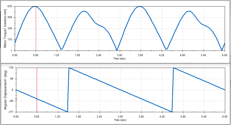
Motor Torque and Displacement of crank graph comparison
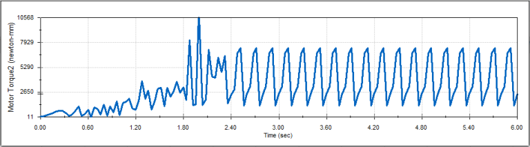
600 RPM Motor Torque Graph
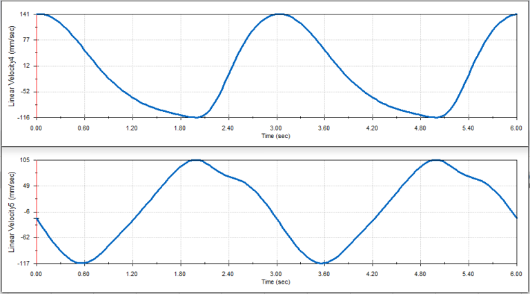
Linear X (top) and Y (bottom) velocity of midpoint of the extension link
Trash Can Assignment
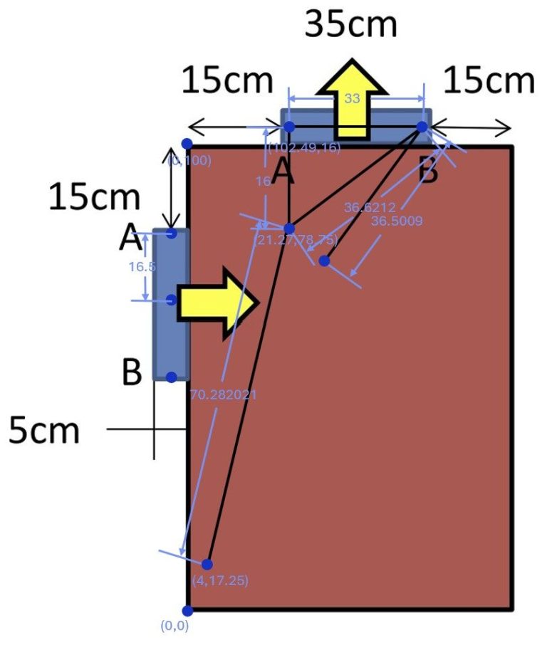
PROJECT OVERVIEW: The goal of this assignment was to study 4 bar linkages and degrees of freedom to design a trash bin that could move a tray of trash from the top of the bin to the garbage slot with out flipping the trash tray. Tasked with using Math Illustrator to find correct measurements then building a model and motion study with correct measurements.
Trash Can Simulation
Design Process
Used Math Illustration Demo to get correct measurements for motion of trash can. After measuremenst were found they were used to make a 3D SolidWorks model and simulation showing how the trash can would work with the correct motion forwards and backwards.
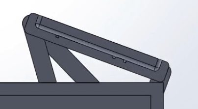
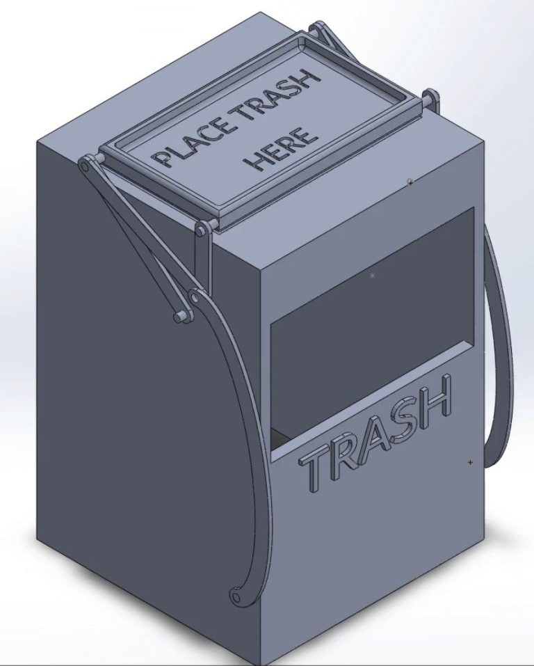
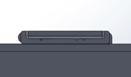
Pictures show Full Trashcan assembly, Math Illustrator measurements, flush tray at starting position, flush tray at end position, and closest contact point between tray and trashcan.